Cosmic Ray Telescope
Well, it’s not really cosmic rays and it’s not really a telescope…
Just as X-rays can be used to view inside a human body, it is possible to use muons to get at least a shadowy image of the hidden interior of intriguing stone structures. This is how the “Big Void” in the Great Pyramid was “discovered” (though it isn’t really discovered until someone like us manages to get a robot or borescope in there.)
Muons are born when cosmic rays from space slam into our upper atmosphere. They rain down on us constantly, passing through everything (including you, right now) like ghosts. But they sometimes get stopped, just as X-rays do. By comparing how many muons we “see” in different places, we can work out whether there is something very solid, or a void, in between us and the source of muons – the sky.
How do we “see” muons? One way is to take a piece of “scintillator” material, in this case a special plastic called BC-408. When a muon interacts with it, the BC-408 gets excited and generates a pulse of deep blue/violet light. It’s only very faint, so we use a very sensitive device – in this case a silicon photomultiplier (SiPM) to view it.
BC-408 is tricky to get hold of in small quantities, but Mark Shropshall at Mi-Net Technology Ltd kindly provided a block from the manufacturer Luxium Solutions. It’s a thing of beauty just on its own.
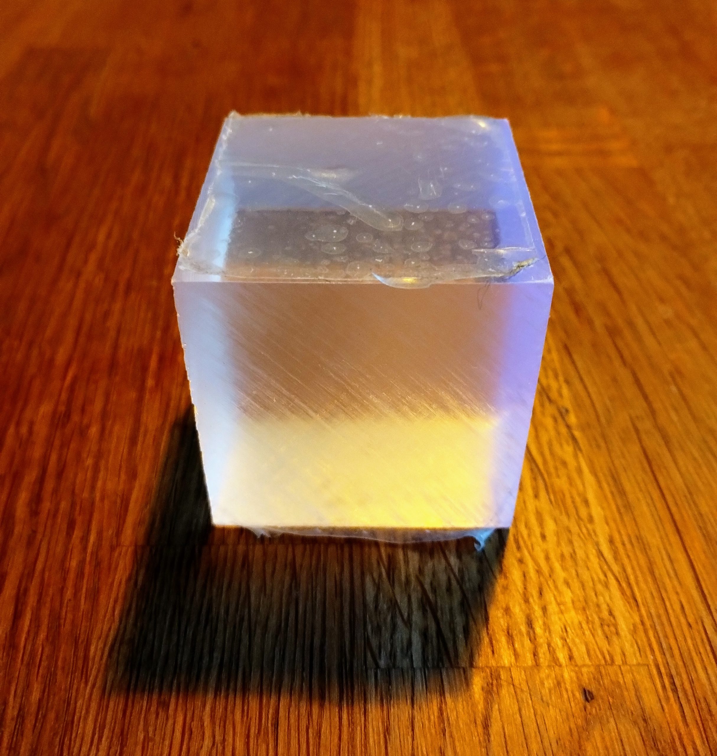
BC-408 – Scintillating!
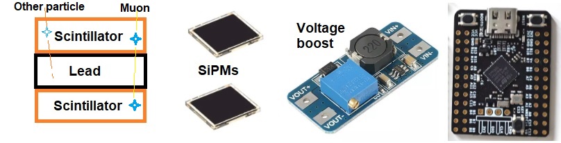
I want to make a sort of telescope. Other high energy particles will excite the scintillator, so to be sure I am capturing muons I am making a sandwich, with a piece of lead as the filling, and two pieces of scintillator as the bread.
For the microcontroller to declare that it has spotted a muon, the top scintillator must flash a short time before the bottom one – this tells it that the particle came from the sky. The piece of lead is to absorb other non-muon particles – which will cause the top scintillator to flash, but not the bottom one.
The aim is to be really clever so that we make the most of the magic inside an STM32G431 microcontroller. Conventional detector front ends need/use bias resistors, load resistors, coupling capacitors, threshold pots, protection diodes, and amplifiers. I’ve got rid of them all – I hope!
The SiPM fast output drives the STM32 comparator input directly (high-impedance match). DACs replace threshold resistors. ADCs replace external measurement. Comparators and TIM2 replace coincidence logic chips. The entire analogue front end is inside the microcontroller, so we just need an MT3608 boost module to provide the required higher voltage to the two MICROFC-60035-SMT-TR SiPMs.
The whole thing is matchbox-sized and component cost is less than £50.
| Component | Part | Cost | Role |
|---|---|---|---|
| Scintillators | BC 408 Plastic × 2 | Donated | Detect muon passage through both layers |
| SiPMs | MICROFC-60035-SMT-TR × 2 | £16 each | Convert scintillation photons to electrical pulses |
| Bias supply | MT3608 boost module | £1.75 | 28–30 V SiPM bias from 5 V input |
| MCU | STM32G431CBU6 (WeAct Mini) | £4 | Hardware coincidence, entropy output, UART to FPGA |
| OCA sheet | F-G6.2-250 | £2.55 | Semi-permanent join SiPM-BC 408 |
I’m writing this as I go along so I don’t know right now if it’s going to work, here’s the detail (you can skip the nerdy bits):
The sandwich – scintillator bread with a lead filling
The sandwich parts were kindly cut, polished and crafted by Len Newton. I had previously worked with Len to create a high speed model test boat for the TWSH project, so I knew he could turn his hand to just about anything! (The TWSH project that aims to create a record-breaking, jet propelled hydrofoil boat that will be awe-inspiring and revolutionary if it lives up to expectations.)

Len cast the lead blocks so that they are very neat and professional, but I suppose the same physics results could be obtained by bonding sheets of lead together. The assembled sandwich is on the right, with windows waiting for the SiPMs to peer into, to spot muon action.
Attaching the Silicon Photomultiplier Diodes to the BC-408
We want to maximise the number of photons passing from the inside of the scintillator to the SiPM diode, so we need to consider the refractive index.
The BC-408 surface has a refractive index of 1.58
The SiPM “window” encapsulant refractive index is 1.59 @ 420 nm
So we want the joint to have a similar refractive index.
If we use typical joining materials with a refractive index of 1.45 to 1.50 then the losses will be a fraction of a percent, which is much better than the losses of several percent that we will get if we have any air gaps.
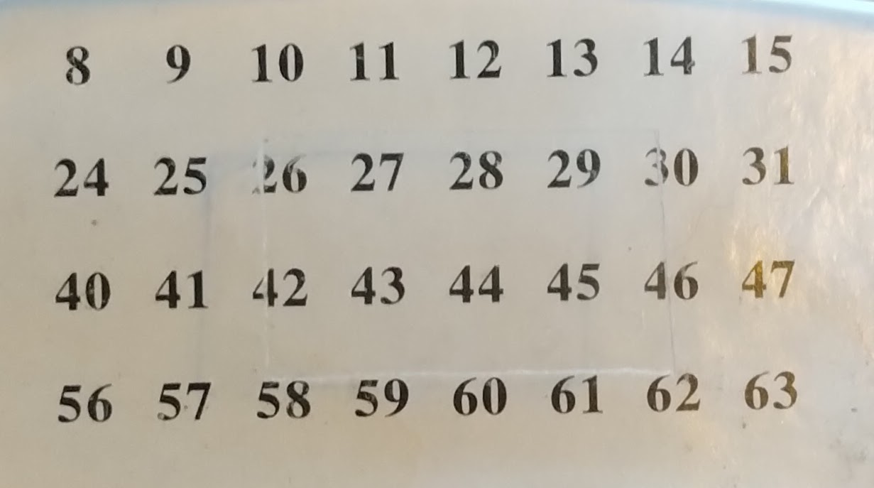
I found Optically Clear Adhesive (OCA) sheets for low cost on EBay. Cheap and effective, it makes a decent bond and the transparency looks good. You can see where the edges of the roughly-cut patch are in the image below, but can you seen any difference between the patch and the rest? I’ll cut squares of this, clean the SiPM and BC 408 surfaces with alcohol, then press then press them all together.
Hardware Coincidence Detection
A muon passing through both scintillators triggers them within nanoseconds. The STM32 hardware comparators (COMP1, COMP2) watch both SiPM fast outputs continuously. When the first fires, TIM2 captures the timestamp via input capture. When the second fires, the ISR calculates the delta. If within 100 ns (17 ticks at 170 MHz), the event is counted. This happens entirely in hardware — the main processor sleeps until a confirmed coincidence.
Current resolution: 5.88 ns ticks (TIM2 at 170 MHz). HRTIM can achieve 2.1 ns if tighter timing is needed.
Active Baseline Restoration
SiPM fast outputs show a voltage dip after each pulse. At low count rates this doesn’t have a big effect. At higher rates the dips add up and the threshold becomes unreliable. So, every 100 ms the firmware samples the SiPM node voltage via ADC and injects a correction through the DAC output on the same wire (PA4 jumpered to PA1 node; PA5 jumpered to PA7).
Self-Healing
The DAC output and SiPM input share a wire, which can sometimes start oscillating — a rapid wobble that looks like thousands of false events. The firmware detects this by taking 20 rapid ADC samples and calculating variance. If variance exceeds OSC_THRESHOLD, the DAC output driver is switched to high-impedance mode (BOFF bit), breaking the feedback loop. After HEALING_RETRY_MS (10 s) of stability, it attempts to reconnect. The process should be fully automatic – maybe!
I might add:
- Dead-time check: add 1 ms debounce in ISR to suppress SiPM recovery double-pulses
- If baselines never reach ~50 mV, invert the compensation sign in comp_mv logic (depends on DAC coupling to node)
The sketch is written, so the next step is to cut the scintillator into 30x30x10mm pieces of bread and add in the 10mm thick lead filling. Each scintillator needs to be surrounded by a reflector that keeps external light out and the nice blue light flashes in.
To be continued….